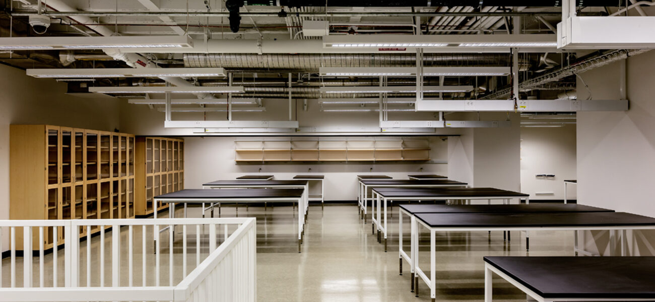
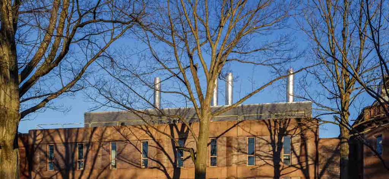
With three research floors and a prime location within the chemistry complex at Yale University, the 70,000-sf Kline Chemistry building has the highest lab and fume hood density on campus. In renovating the 50-year-old building, the mission was to modernize the lab space while significantly improving building efficiency. In addition to a new building envelope and HVAC systems, conservation strategies include more efficient fume hood use, reduced air changes and power watt densities, minimized outside air and reheat, occupancy controls, and hood proximity sensors. As a result of these efforts, the building is projected to achieve a 30 percent energy cost savings for LEED, and to consume 35 percent less energy than other Yale laboratories. When reductions in fume hood outdoor air demand are included, cost savings are projected to be up to $500,000 beyond those in a typical code-compliant laboratory in this climate zone.
“Yale challenged the project team to take an unconventional approach and break the mold for lab design on campus, with the goal of dramatically cutting energy and operating costs for this building compared to other labs at Yale,” says Thomas Stella, senior associate for building mechanical systems for WSP in Boston.
Non-traditional Metrics
Though the building retains the original floor plate—the new design arranges program specifics by floor: biology labs on the first floor; organic chemistry on the second floor; and the building’s instrument center, including the X-ray and large magnet instrument centers and MEP services entrance, on the basement level—the redesign departs from traditional lab design practices. “To significantly reduce annual energy and operational cost, it was necessary to challenge every assumption that has been standard practice in lab design for decades,” says Stella. This was done by looking at best practices from a national level to detailed review of operational performance of the Yale labs.
The project work plan includes:
- Challenging design criteria based on data analysis
- Optimizing every component of the design, informed by simulation and modeling
- Using data visualization tools with advanced graphics and analytics to make it easy to see, change, and improve building operating parameters
In a chemistry lab with four 8-foot fume hoods, the question challenging designers is what hood operational diversity is appropriate at the room level and the building level. Based on analysis of several months worth of fume hood use data in the neighboring Chemistry Research Building (CRB) and other labs, the new infrastructure design assumes that an average of only two hoods in the lab will operate at once, though four fume hoods can operate simultaneously at the room level.
“Although the chemistry users initially told us there are many times of day when all four hoods are in use, our data showed this was rarely the case. We foresee that at peak times, generally only two and possibly three, hoods were in use. That determination drove the design,” says Stella.
They analyzed the possibility to reduce the air changes per hour (ACH) in the Kline Chemistry lab from the previous minimum criteria of 9 ACH, and hood face velocities of 100 feet per minute (fpm) at an 18-inch sash opening. Using computational fluid dynamics (CFD) modeling, the various lab types and configurations were modeled to maximize operational and air quality performance. Working with Yale’s Occupational Environmental Health and Safety group (OEHS), they welcomed the opportunity to utilize low-flow hoods after a detailed review of manufacturer’s product during the procurement process. The lower air flow requirements of the high-performance hoods showed, through the CFD modeling, that hood capture was superior at the lower air flow requirement for the four 8-foot hoods.
The modeling, through various air terminal design iterations, also yielded superior comfort and air quality performance as the design layouts were informed by the modeling results. “Because we would not have four hoods operating at once, capture at the operational hoods would be improved even further,” says Stella. “We determined it was safe to operate at a lower velocity for these lab configurations. The lab opened in the spring of 2014 operating at a mid-range velocity of 80 fpm, with the ability for lab operators to reduce it to 60 fpm.
A similar modeling exercise proved beneficial in the biology lab, where design is traditionally based on cooling load rather than air-change rates. “We thought the biology labs would be cooling-load driven, but they ended up being air-change driven. The CFD model pointed us to direct more air near the room perimeter to promote mixing the air,” says Stella. The initial layout called for low exhaust to clear air near the floor of the room in a spill scenario, but this design did not work due to the existing poured concrete construction and structural columns. The final design moves all heat-generating equipment to the room perimeter. As warm air from the equipment rises into a perforated ceiling, the exhaust pulls it out of the room before it has a chance to heat up the rest of the lab.
In the lab areas, efforts to reduce outside air demand are estimated to achieve a 35 percent reduction in peak outside air, $10 per square foot (psf) savings in construction cost, and 22 percent energy cost savings.
Realizing that existing lab buildings on campus were using less power within the lab proper than they were designed for, Yale undertook a metering study to determine their real lab power profile. Armed with this information, the power densities in the new Kline are based on analyzing one month of data from electrical metering installed in lab zones, shared equipment areas, combined spaces, and office/corridor areas in other similar lab buildings at Yale. This empirical data showed much lower usage than expected.
Compared to old designs that used power estimates of up to 10 watts psf in open labs and 20 watts psf in shared support areas, the actual usage in the open lab was metered at an average of 2 watts psf, with a peak demand of 4.3 and 5.8 watts psf; the shared support areas had a peak demand of 9.9 watts psf. The final equipment peak design was a compromise of 7 watts psf in open labs and 12 in the shared support space.
“The challenge by Yale to right-size not only power density criteria, but all aspects of the mechanical and electrical systems and equipment selections, was the key to the drastic energy reduction in the building-wide solution, and it challenged the status quo,” says Stella.
Conservation Strategies
Energy modeling informed the design process, in accordance with Yale’s sustainability targets based on LEED 2009 and ASHRAE 90.1-2007, requiring all campus construction and renovation projects to meet LEED Gold standards and achieve a 30 percent energy cost savings. “In a project like this, there is no silver bullet that results in a drastic amount of energy savings. You have to relentlessly scrutinize every aspect of the project and combine energy efficiency measures to add up to a larger savings,” says Roselin Osser, building performance specialist with WSP’s Built Ecology group.
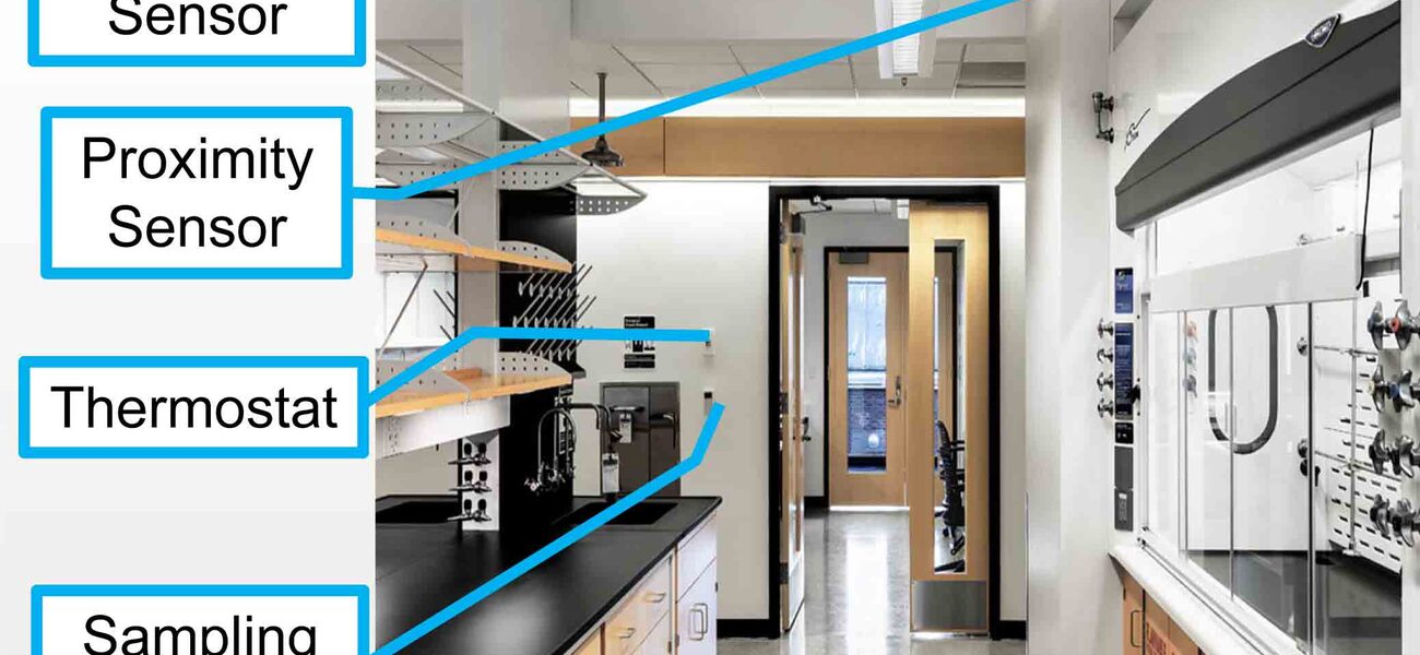
The following measures helped achieve the 30 percent energy reduction: envelope improvements with curtain wall; lighting power density reduction and occupancy sensors; airflow reductions from proximity sensors; fan pressure reductions; chilled beams in instrumentation rooms, by reducing the need for outdoor air; and optimized glycol heat recovery. In addition, HVAC occupancy sensors control lighting and temperature during unoccupied periods to avoid overly heating and cooling empty spaces. The controls provide options for three room modes: occupied, unoccupied, and standby. Standby, the default mode during regular lab hours, relaxes the room temperature setbacks during periods when the room is empty, but reverts to standard setback temperature and air changes when the lab is unoccupied at night.
The laboratory uses optimized air handling unit zoning for additional energy efficiency. One air handling unit serves the second-floor chemistry lab with a high air change rate, while another serves first-floor biology labs and basement instrument labs, which have lower air change rates. Both air handling units provide 100 percent outdoor air, as is typical for a laboratory. This strategy of grouping areas with similar schedules, air changes, and cooling loads allows the use of supply air temperature optimization to minimize reheat. Supplemental air handling units, using primary air from the biology/instrument lab air handling unit, are used to meet the instrument lab’s high equipment-driven cooling loads by adding cooled, recirculated air.
An Aircuity® system monitors the levels of chemical compounds in occupied lab areas via a sampling port, allowing the university to continuously monitor air quality, with options to adjust air supply and exhaust rates based on indoor contaminant levels. The automated system samples and analyzes pockets of air, which are routed to a centralized suite of sensors. “Currently, the system is not linked directly to an operation for controlling the air changes, but it allows the University to monitor those chemicals and to collect data that could be used to inform decisions about reducing lab airflow rates in the future,” says Osser.
The Kline Chemistry project includes an advanced graphics and analytics system for detailed monitoring and continuous improvement of daily operations. It monitors and displays temperature, fume hood operation, lighting, and occupancy, allowing the facilities department to track performance and make adjustments as needed. Simple, color-coded graphics provide operational insight into how the building is working. For example, a floor plan shows whether temperature setpoints in each room are being met: Green means setpoints are met, red means the room is too hot, and blue means the room is too cold. “Instead of having to look at each room to see what is going on, you can look at it globally, with the colors doing the work for you. When you see red, you know where to investigate and not waste time on the rooms doing well,” says Stella.
The system is pre-programmed for parameters that would normally be time consuming to change, such as maximum and minimum air changes, and taking a lab out of service. All can be done by pressing a button rather than re-programming each one. “With the automated system, it is possible to visualize buildings down to the room level and easily make adjustments or global changes. Instead of re-programming parts and pieces of the lab to improve efficiency, you can click a button,” says Stella. “By making stuff easy to change, you get the energy savings over the life of the building.”
By Mary Beth Rohde
This report is based on a presentation Osser and Stella made at Tradeline’s College and University Science Facilities 2014 conference.


